E-Beam Evaporator System [KVE-E2000 Series] > E-BEAM Series
-
제품 정보
제품 상세설명
Overview
An evaporator uses an electric resistance heater or high-energy beam to melt material
and to raise its vapor pressure to a useful range. This process takes place in a high
vacuum state to allow the vapor to reach the substrate without reacting with or
scattering against other gas-phase atoms in the chamber while reducing the
incorporation of impurities from the residual gas in the vacuum chamber. The KVE Series
evaporation systems are capable of fabricating multi-layer thin films by applying this
co-deposition process.
Features
≻ Excellent Thickness Uniformity
The KVE Series KVE-E2000 System provide excellent thickness uniformity of
resultant films even for substrates that have the same diameter as the sputtering cathode assembly
≻ No loadlock chamber
≻ Semi-auto system control by PLC
-
Specifications
제품 Specifications
Specifications
ITEM
SPECIFICATIONS
Process Chamber
Stainless steel
Vacuum Pumping Station
Cryo / TMP
Loadlock Chamber
N/A
Substrate Unit
Rotation / Heating / Cooling
Sample Size
4inch ~
Vacuum Gauge Controller
ATM ~ 1.0E-10Torr
Power Supply Unit
6kW, 8kW, 10kW
Crucible Size
4cc, 7cc, 15cc, 25cc
Pocket Number
Single, 4, 6
Film Thickness Uniformity
< ± 2.99%
Ultimate Pressure
< 1.99E-7Torr
System Control
PLC based Semi-auto
-
Options
제품 Options
Options
- UHV Type Chamber(Less than 9.90E-9 Torr)
- Loadlock Chamber
- Power Selection
- Substrate Heating/Cooling
- Lift-Off plate
- Automatic Control
- Etc... user requirements
Options
- UHV Type Chamber(Less than 9.90E-9 Torr)
- Loadlock Chamber
- Power Selection
- Substrate Heating/Cooling
- Lift-Off plate
- Automatic Control
- Etc... user requirements
-
Control
제품 Control
System Control
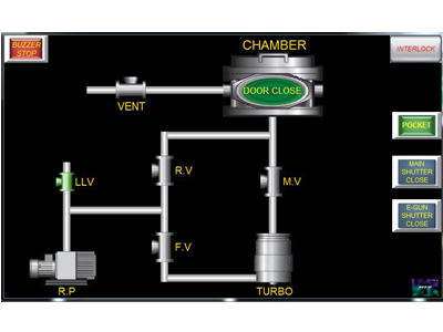
Pumping
The figure shows the pumping screen. Pumping screens have valves and pumps. The pump and valve are easily operated with one touch.
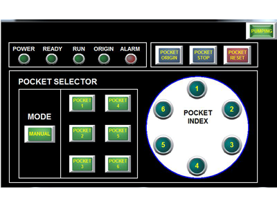
Pocket
The picture shows the pocket screen. When you press the poc ket button on this screen, the e-beam index rotates and you can see the source you selected.
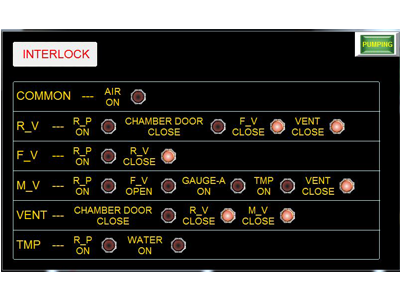
Interlock
This picture shows the interlock screen. Basically, the interlock is set so that it does not work when you deviate from the correct method of use for your safety.
System Control
Pumping
The figure shows the pumping screen. Pumping screens have valves and pumps. The pump and valve are easily operated with one touch.
Pocket
The picture shows the pocket screen. When you press the poc ket button on this screen, the e-beam index rotates and you can see the source you selected.
Interlock
This picture shows the interlock screen. Basically, the interlock is set so that it does not work when you deviate from the correct method of use for your safety.
-
사용후기
-
상품문의
-
배송/교환정보
[배송]
배송 안내 입력전입니다.[교환]
교환/반품 안내 입력전입니다.
선택된 옵션
-
E-Beam Evaporator System [KVE-E2000 Series]+0원
![Glancing Angle Deposition System [KVE-EG Series]](https://www.koreavac.com/data/item/1700481677/thumb-15082034061_400x350.png)
![E-Beam Evaporator System with Loadlock [KVE-E2000L Series]](https://www.koreavac.com/data/item/1754887020/thumb-15082033681_400x350.png)
![E-Beam Evaporator System with Loadlock [KVE-E4000L Series]](https://www.koreavac.com/data/item/1754887402/thumb-15082032901_400x350.png)
![E-Beam Evaporator System [KVE-E4000 Series]](https://www.koreavac.com/data/item/1754887674/thumb-150820318711_400x350.png)
![Dual E-Beam Co-Deposition System [KVE-ED Series]](https://www.koreavac.com/data/item/1779840252/thumb-GladDualEBeam23KVS008_400x350.png)