KVET-I2000L > ETCHER
-
제품 정보
제품 상세설명
Overview
An Inductively Coupled Plasma (ICP) is a type of plasma source in which the energy is
supplied by electrical currents produced by electromagnetic induction; that is, by time-
varying magnetic fields. In its simplest form, an inductively coupled plasma consists of a
vacuum vessel, into which the gas to be ionized is administered, and an induction coil,
driven by a source of RF power. The coil is generally separated from the vacuum region
by a dielectric window. The wide range of applications for RF-driven, inductively
coupled plasma sources has recently expanded into processing tools for coating or
etching systems in the microelectronics industry.
-
Specifications
제품 Specifications
Specifications
ITEM
SPECIFICATIONS
System configuration
R&D
Substrate size
2” - 6” (50.8mm - 150mm)
Etch Uniformity
1.06±% within 3” wafer
Etch rate
1.16µm/min
Process Chamber
Al anodized Chamber
Substrate
He backside cooling / Bias / Chiller (-20℃ ~ 50℃)
Source
ICP source with plasma spiral coil
Specifications
ITEM
SPECIFICATIONS
System configuration
R&D
Substrate size
2” - 6” (50.8mm - 150mm)
Etch Uniformity
1.06±% within 3” wafer
Etch rate
1.16µm/min
Process Chamber
Al anodized Chamber
Substrate
He backside cooling / Bias / Chiller (-20℃ ~ 50℃)
Source
ICP source with plasma spiral coil
-
Options
-
Control
제품 Control
System Control
Pumping
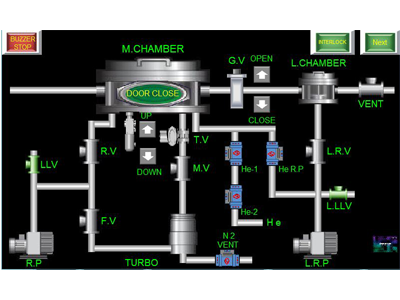
The figure shows the pumping screen. Pumping
screens have valves and pumps. The pump and valve
are easily operated with one touch.
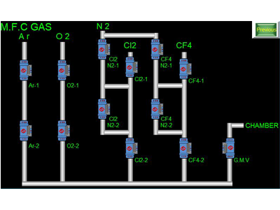
Gas Control
This picture shows the gas control screen.
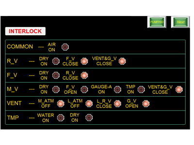
Interlock
This picture shows the interlock screen. Basically, the
interlock is set so that it does not work when you
deviate from the correct method of use for your safety.
System Control
Pumping
The figure shows the pumping screen. Pumping
screens have valves and pumps. The pump and valve
are easily operated with one touch.
Gas Control
This picture shows the gas control screen.
Interlock
This picture shows the interlock screen. Basically, the
interlock is set so that it does not work when you
deviate from the correct method of use for your safety.
-
사용후기
-
상품문의
-
배송/교환정보
[배송]
배송 안내 입력전입니다.[교환]
교환/반품 안내 입력전입니다.
선택된 옵션
-
KVET-I2000L+0원